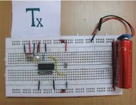


This circuit uses RF module to control DC motors through a motor driver IC L293D. Transmission is enabled by giving a low bit to pin14 (TE, active low) of encoder HT12E. The controls for motor are first sent to HT12E. Pins 10 and 11 (D0-D1) are used to control one motor while pins 12 and 13 (D2-D3) to control another motor. The data signals of encoder HT12E work on negative logic. Therefore a particular signal is sent by giving a low bit to the corresponding data pin of encoder.
The parallel signals generated at transmission end are first encoded (into serial format) by HT12E and then transferred through RF transmitter (434 MHz) at a baud rate of around 1-10 kbps. The same signals are acquired by RF receiver after which it is decoded by HT12D. For more details, refer RF remote control.
Since the encoder/decoder pair used here works on negative logic, the decoded signals are fed to an inverter (NOT gate) IC 74LS04. The proper (inverted) signals are then supplied to L293D. L293D contains two inbuilt H-bridge driver circuits to drive two DC motors simultaneously, both in forward and reverse direction.
The motor operations of two motors can be controlled by input logic at pins 2 & 7 and pins 10 & 15. Input logic 00 or 11 will stop the corresponding motor. Logic 01 and 10 will rotate it in clockwise and anticlockwise directions, respectively. Thus, depending upon the signals generated at the transmission end, the two motors can be rotated in desired directions.
| Doc | Project details | ||
| Source Code | Complete Circuit Diagram files |